
Mahjong Score Card Device
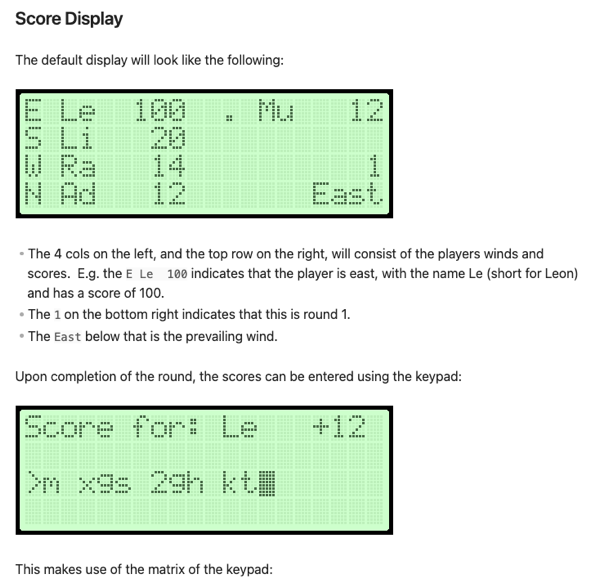
I’ve recently started playing Mahjong with my family. We’ve learnt how to play a couple of years ago and grown to like it a great deal. I’m not sure if you’re familiar with how the game is scored, and while it’s not complicated, there’s a lot of looking things up which can make scoring a little tedious. So my dad put together a Mahjong scoring tool in Excel. You enter what each player got at the end of a round — 2 exposed pungs of twos, 1 hidden kong of eights, and a pair of dragons, for example — and it will determine the scores of the round and add them to the running totals. It also tracks the winds of the players and the prevailing winds, which are mechanics that can affects how much a player can get during a round. The spreadsheet works quite well, but it does mean we need to keep a bulky laptop around whenever we play.
I wondered if the way we calculated and tracked the scores could be improved. I could do something like build a web-style scorecard, like I did for Finska, but it gets a little boring doing the same stuff you know how to do pretty well. No, if I wanted to do this, I wanted to push myself a little.
I was contemplating building something with an Arduino, maybe with a keypad and a LCD display mounted in a case of some sort. I’ve played around with LCD displays using an Arduino before so it wasn’t something that seemed too hard to do. I was concerned about how well I could achieved the fit and finished I wanted this to have to be usable. Ideally this would be something that I can give to others to use, not be something that would just be for me (where’s the fun in that?). Plus, I didn’t have the skills or the equipment to mount it nicely in an enclosed case that is somewhat portable. I started drawing up some designs for it, but it felt like something I wouldn’t actually attempt.
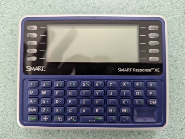
One day I was perusing the web when I came across the SMART Response XE. From what I gathered, it a device that was built for classrooms around the early 2010s. Thanks to the smartphone, it didn’t become super successful. But hobbyist have managed to get their hands on them and reprogram them to do their own thing. It’s battery powered, had a full QUERTY keyboard and LCD display, is well built since it was designed to be used by children at schools, and feels great in the hand. And since it has an Atmel microprobes, it can be reprogrammed using the Arduino toolchain. Such a device would be perfect for this sort of project.
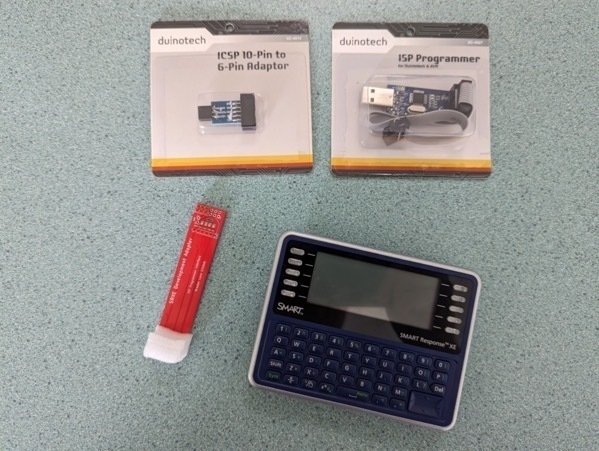
I bought a couple, plus a small development adapter, and set about trying to build it. I’ll write about how I go about doing it here. As the whole “work journal” implies, this won’t be a nice consistent arc from the idea to the finished project. I’m still very much a novice when it comes to electronics, and there will be setbacks, false starts, and probably long periods where I do nothing. So strap in for a bit of bumping around in the dark.
First Connection Attempt
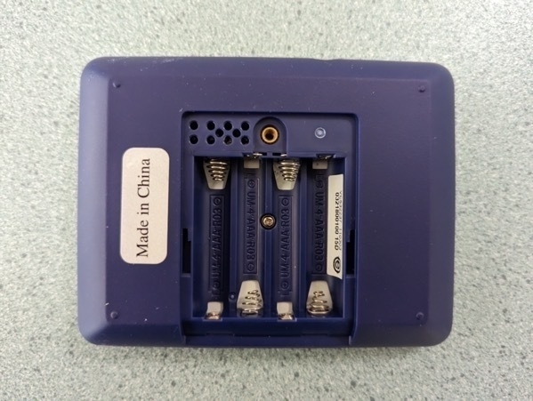
The way to reprogram the board is to open up the back and slot some pins through the holes just above the battery compartment. From my understanding, these holes expose contact pads on the actual device board that are essentially just an ISP programming interface. In theory, if you had an ISP programmer and a 6 pin adapter, you should be able to reprogram the board.
The first attempt of attempting to connect to the SMART Response XE was not as successful as I hoped. For one thing, the SRXE Development Adapter was unable to sit nicely within the board. This is not a huge issue in and of itself, but it did mean that in order to get any contact with the board, I would have to push down on the device with a fair bit of force. And those pogo pins are very fragile. I think I actually broke the tip of one of them, trying to use an elastic band and tape to keep the board onto the . I hope it does not render the board useless.
The other issue I had is that the arrangement of the 6 pin header on the developer board is incompatible with the pins of the ISP programmer itself. The pins on the ISP programmer are arranged to plugin directly to an Arduino, but on the development board, the pins are the the wrong way round. The left pin on both the male pin on the board and female socket from the IVR programmer are both Vcc, when in order to work, one of them will need to be a mirror image of the other. This means that there’s no way to for the two to connect such that they line up. If the pins on the SMART Response XE were on the back side of the board, I would be able to plug them in directly.
I eventually got some jumper wires to plug the ISP programmer into the correct pins. Pushing down on the board I saw the LEDs on the adapter light up, indicating activity. But when I tried to verify the connection using avrdude, I got no response:
$ avrdude -c usbASP -p m128rfa1

avrdude: initialization failed, rc=-1
         Double check the connection and try again, or use -F to override
         this check.


avrdude done.  Thank you.
So something was still wrong with the connection. It might have been that I’ve damaged one of the pins on the dev board while I was trying to push it down. I’m actually a little unhappy with how difficult it is to use the adapter to connect to the device, and I wondered if I could build one of my own.
Device Adapter Mk. 1
I set about trying just that. I wanted to be able to sit the device on top of it such that the contact points on the board itself will sit on the adapter. I was hoping to make the pins slightly longer than the height of the device such that when I rest it on the adapter, the device was slightly balanced on top of the pins and the board will make contact with gravity alone.
This meant that the pins had to be quite long and reasonably sturdy. Jaycar did not have any pogo pins of the length I needed (or of any length) so I wondered if the pins from a LED would work1. I bought a pack of them, plus a prototyping board, and set about building an adapter for myself. Here the design I came up with:
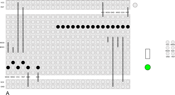
And here is the finished result:
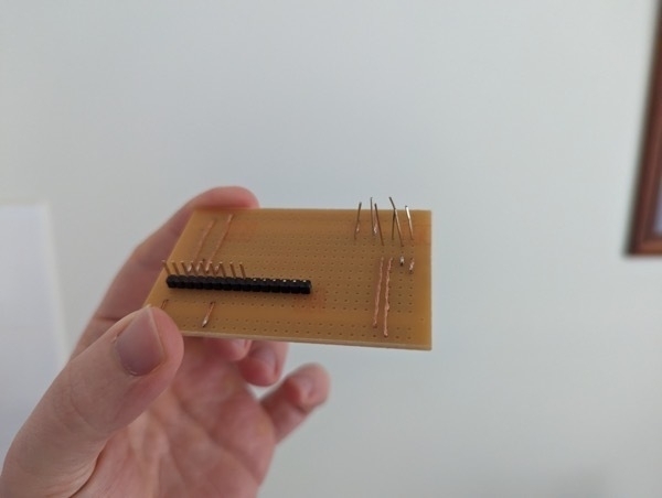
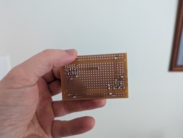
And it’s a dud! The position of the header gets in the way of where the device lines up to rest on the pins. But by far the biggest issue is the pins themselves. I tried placing them in the holes and rested the circuit board on top with a small spacer while I was soldering them. The idea is that after removing the spacer the pins will be higher than the device. I was hoping to cut them down to size a little, but I cut them unevenly, which meant that some of the pins won’t make contact. When I try resting the device on the board I get no rocking, which means that I suspect none of the pins make contact. I’m still not happy with the LED pins either. They don’t seem strong enough to take the weight of the device without bending.
The best thing about it was the soldering, and that’s not great either. I’m not sure I’ll even try this adapter to see if it works.
Next Steps
Before I create a new adapter, I want to try to get avrdude talking with the board first. I think what I’ll try next is resting some nails in the holes and attaching them to alligator clips hooked up to the ISP programmer. If this works, I see if I can set about building another board using the nails. I won’t use the header again as I think it will just get in the way. It might be enough to simply solder some hookup wires directly onto the prototyping board.
Anyway, more to come on this front.
Update 29 Oct 2023: I haven’t revisited this project since this post.
-
I couldn’t find any decent bridging wire at Jaycar either so I used reclaimed wire from a CAT-5 cable. I stripped the insulation completely, twirled the wires, and soldered them onto the contacts. It worked really well. ↩︎